How to Generate Internal (Ring) Gear Profiles Online — Fellow Cutter Method & DXF Export
Internal gears are the heart of every planetary gearbox, yet almost no free tool can draw one correctly. This guide explains internal (ring) gear geometry, the Fellow pinion-cutter generation method, and how to export a production-ready SVG or DXF ring gear in your browser.
Key Takeaways
- An internal gear (ring or annulus gear) has teeth cut on the inside of a ring; the tooth tips point toward the centre.
- Unlike an external gear, the tip circle is smaller than the pitch circle and the root circle is larger — the addendum points inward.
- Internal gears are generated with a Fellow pinion-cutter (gear shaper), not a rack. The cutter must have fewer teeth than the ring: z₁ < z₂.
- The generation follows Willis kinematics: the ring is fixed while the cutter orbits and rotates about its own axis in a fixed ratio.
- GearProfile.app produces the ring gear by boolean hobbing (Raw export) or analytic NURBS SPLINE curves (High Quality export), exportable to SVG and DXF.
What Is an Internal (Ring) Gear?
An internal gear — also called a ring gear or annulus gear — is a gear whose teeth are cut on the inside surface of a ring rather than on the outside of a disc. When you look at one face-on, you see an annular ring with teeth pointing inward toward the centre.
Internal gears always mesh with an external pinion that sits inside the ring. Because both gears rotate in the same direction (unlike an external pair, which counter-rotate), and because the meshing teeth are curved the same way, an internal gear pair offers several advantages: a higher contact ratio, a more compact centre distance, and greater load capacity for the same size. These properties are exactly why the internal gear is the structural core of the planetary (epicyclic) gearbox.
Like an external gear, the working flank of an internal gear tooth is an involute of a base circle (rb = rpitch · cos α). The same rule of meshing applies: an internal gear and its pinion must share the same module (or diametral pitch) and the same pressure angle.
External vs Internal Gears: Key Differences
The internal gear is, in a sense, an external gear turned inside out. That single inversion flips several geometric relationships that trip up first-time designers:
| Property | External gear | Internal (ring) gear |
|---|---|---|
| Tooth direction | Points outward | Points inward, toward the centre |
| Tip (addendum) circle | Larger than pitch circle | Smaller than pitch circle |
| Root (dedendum) circle | Smaller than pitch circle | Larger than pitch circle |
| Tooth space vs tooth | Tooth is solid material | Tooth space is solid; the "tooth" is a cut-out |
| Meshing direction | Counter-rotating | Same direction as pinion |
| Generation tool | Rack (hob) cutter | Fellow pinion-cutter (gear shaper) |
Because the addendum of an internal gear points inward, the tip diameter da2 is smaller than the pitch diameter d₂, and the root diameter df2 is larger. This is the reverse of the external case and is the single most important thing to keep in mind when interpreting a ring-gear drawing.
The Fellow Cutter Method & Willis Kinematics
You cannot cut an internal gear with a rack or a standard hob — there is no room for the tool to run out inside the ring. Instead, internal gears are cut with a Fellow pinion-cutter (named after the Fellows Gear Shaper Company), a hardened gear-shaped cutter that reciprocates axially while slowly rotating in mesh with the workpiece. This process is called gear shaping.
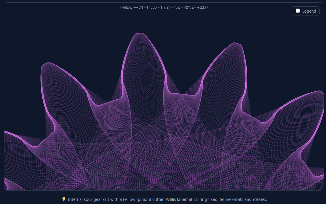
Mathematically, the generated ring-gear flank is the envelope of all the successive positions of the cutter tooth as it rolls in mesh with the ring blank. GearProfile.app reproduces this envelope digitally using Willis kinematics:
- The ring gear (z₂) is held fixed.
- The cutter (z₁) orbits around the ring centre at an angle t, its centre tracing a circle of radius equal to the centre distance a.
- Simultaneously the cutter rotates about its own axis by −(z₂/z₁ − 1)·t, keeping the two pitch circles rolling without slip.
Sweeping the cutter through a full turn and subtracting every cutter footprint from the ring blank leaves precisely the internal tooth profile — including the true trochoidal root fillet generated by the cutter tip, which a naive "involute-only" construction would miss.
The centre distance for a standard (equal profile-shift) pair is:
a = m · (z₂ − z₁) / 2
Because the cutter must have fewer teeth than the ring and needs clearance to generate a clean fillet, GearProfile.app enforces z₁ < z₂ and a minimum difference of z₂ − z₁ ≥ 3. Choosing z₁ too close to z₂ causes trimming (secondary interference), where the cutter removes part of the involute flank it was supposed to leave.
Internal Gear Parameters Explained
Generating a ring gear needs one extra parameter compared to an external gear — the cutter tooth count z₁ — because the fillet shape depends on which cutter produced it.
| Parameter | Symbol | Typical range | What it controls |
|---|---|---|---|
| Module or diametral pitch | m / DP | 0.5 – 10 mm / 2.5 – 50 DP | Tooth size. Pitch diameter d₂ = m · z₂ (metric) or z₂ / DP inches (imperial). Ring and pinion must match. |
| Ring tooth count | z₂ | 15 – 100 | Number of teeth on the ring. Sets pitch diameter and gear ratio. |
| Cutter tooth count | z₁ | 5 – (z₂ − 3) | Teeth on the Fellow cutter. Must be at least 3 fewer than z₂. Affects the root fillet shape. |
| Pressure angle | α | 14.5°, 20°, 25° | Contact-force angle. 20° is the standard (ISO 53). Must match the mating pinion. |
| Addendum coefficient | ha* | 1.0 – 1.25 | Cutter addendum, which becomes the ring's inward tip. DIN 1829 default is 1.25. |
| Dedendum coefficient | hf* | 0.5 – 1.0 | Cutter dedendum. DIN 1829 default is 1.0 for internal cutters. |
| Profile shift | x | −1.5 – +1.5 | Radial cutter shift. Adjusts tooth thickness and avoids interference in tight ratios. |
Choosing the cutter tooth count z₁
In real manufacturing the cutter is a fixed tool, so z₁ is dictated by what is on the shelf. When designing digitally you have freedom, but two guidelines help: keep z₂ − z₁ ≥ 3 to avoid trimming, and prefer a cutter reasonably close to the pinion you will actually run in the ring, since that produces the most representative fillet. For a first pass, a cutter of z₁ ≈ z₂ − 5 works well.
Step-by-Step: Generating a Ring Gear Online
- Select "Internal Spur (Fellow)" at the top of the sidebar. The cutter tooth-count slider (z₁) and the ring tooth-count field (z₂) appear, and the addendum/dedendum defaults switch to the DIN 1829 internal values automatically.
- Choose your size standard. Use Module (mm, ISO) or switch to Diametral Pitch (1/in, AGMA) if you work in imperial units.
- Set the ring tooth count z₂ — the number of teeth on your ring gear.
- Set the cutter tooth count z₁. Keep it at least 3 below z₂. A warning appears if z₁ ≥ z₂.
- Leave the pressure angle at 20° unless your mating pinion uses a different value.
- Preview. The Single Tooth and 360° tabs render the live Fellow-cutter simulation, showing the pitch, base, tip (inner) and root (outer) circles with exact diameters in your selected unit.
- Export. Open Raw Export or High Quality Export, click Calculate, then download SVG or DXF.
The 360° preview is worth a second look: it shows the cutter sweeping every position around the ring, so you can immediately see whether your z₁/z₂ combination produces a clean profile or interferes.
Where Internal Gears Are Used
Planetary (epicyclic) gearboxes
The ring gear is the outer member of every planetary set. Sun, planets, and ring share one module and pressure angle; the ring's internal teeth mesh with the planet gears. Planetary gearboxes deliver high reduction ratios in a compact, coaxial, load-sharing package — used in automatic transmissions, wind-turbine drivetrains, robotics joints, and electric-drive reducers.
Strain-wave and cycloidal reducers
Many high-ratio robotics reducers use an internally toothed ring as the fixed reaction member. An accurate internal profile is essential to their low backlash.
Internal ring gears for hobby and repair
3D-printed planetary gearboxes, camera-slider drives, clock mechanisms, and replacement ring gears for discontinued equipment all need a correct internal profile that most free tools cannot produce.
Interference in Internal Gears
Internal gears are more prone to interference than external pairs, and this is the single biggest reason a ring gear that looks fine on screen can fail to assemble or run. Interference is a physical overlap between the mating tooth surfaces (or between the cutter and the workpiece during manufacture). With internal gears there are three distinct types, each governed by a different geometric limit.
1. Involute interference
Involute interference happens when the tip of one gear digs into the non-involute (below-base-circle) region of the mating tooth. In an internal pair it becomes a problem when the external pinion has few teeth and the internal gear is small. The governing condition is that the internal gear's tip circle must stay larger than its base circle (da2 ≥ db2); for a standard 20° internal gear this only holds once the ring has more than 34 teeth (z₂ > 34). Below that, extra care with profile shift and pinion tooth count is needed.
2. Trochoid interference
Trochoid interference occurs between the tip of the external pinion and the trochoidal root fillet of the internal gear during recess action. It is driven by the difference in tooth counts: the closer z₁ and z₂ are, the more likely it is. For a standard 20° mesh, trochoid interference is avoided when the difference exceeds nine teeth — z₂ − z₁ > 9. This is exactly why a ring gear and its pinion are rarely designed with only a few teeth of difference.
3. Trimming interference
Trimming interference is a radial interference: when z₁ and z₂ are very close, the pinion and ring cannot be pushed together radially at all — they can only be assembled by sliding one into the other axially. The same phenomenon appears during manufacture: cutting an internal gear with a pinion-type shaper cutter whose tooth count is too close to the ring will trim away part of the involute and can break the tooling. Published cutter limits (KHK) show that, for a standard unshifted 20° pinion cutter, involute interference between the cutter and the ring appears for cutter tooth counts of roughly z₀ = 15–22, and each cutter size has a maximum ring tooth count it can safely generate.
| Interference type | Where it acts | Driven by | Rule of thumb (α = 20°) |
|---|---|---|---|
| Involute | Tip vs below-base-circle flank of the mate | Small pinion / small ring | Ring tip > base circle → z₂ > 34 |
| Trochoid | Pinion tip vs internal root fillet | Small tooth-count difference | z₂ − z₁ > 9 |
| Trimming | Radial assembly & cutter generation | z₁, z₂ very close | Keep a large margin; check cutter limits |
Export: Raw Hobbing vs High Quality NURBS
GearProfile.app offers the same two export philosophies for internal gears as for external ones, and the distinction matters even more here because the root fillet of a ring gear is a genuine trochoid.
Raw Export — boolean hobbing
Raw export runs the full Willis-kinematics simulation: the Fellow cutter is swept through a complete orbit and every footprint is boolean-subtracted from the ring blank using a robust 2D geometry engine. The result is the exact manufactured profile, including all secondary trimming, exported as a dense polyline (LWPOLYLINE in DXF). This is the faithful "as-cut" geometry — ideal when you want to see exactly what a real gear shaper would produce.
High Quality Export — analytic NURBS SPLINE
High Quality export computes each tooth section analytically — the involute flank and the trochoidal root fillet are each fitted with a B-spline, and the tip and root arcs are stored as true circular arcs. The DXF then contains smooth SPLINE and ARC entities rather than line segments. Import it into FreeCAD, Fusion 360, or SolidWorks and the extruded ring has smooth, analytically defined faces — the right choice for CAD modelling, FEA, and precision CNC.
Generate an Internal Ring Gear — Free in Your Browser
Switch to Internal Spur, set your ring and cutter teeth, and export SVG or DXF instantly. No installation, no account required.
Open Gear Generator →FAQ
Why does the cutter need fewer teeth than the ring gear?
The Fellow cutter rolls in mesh with the ring like a pinion inside an annulus. For the pair to mesh at all, the pinion (cutter) must have fewer teeth than the ring. A difference of at least 3 teeth (z₂ − z₁ ≥ 3) is required to avoid secondary trimming, where the cutter removes part of the involute it should have generated.
Why is the tip diameter smaller than the pitch diameter?
On an internal gear the addendum points inward, toward the centre. So the tip (addendum) circle sits inside the pitch circle and the root (dedendum) circle sits outside it — the reverse of an external gear. This is normal and correct for a ring gear.
Will my internal gear mesh with a given pinion?
An internal gear and its pinion mesh when they share the same module (or diametral pitch) and the same pressure angle, and the centre distance equals a = m·(z₂ − z₁)/2 for a standard pair. The pinion tip must clear the ring root, and the difference z₂ − z₁ must be large enough to avoid interference — generally z₂ − z₁ ≥ 10 for a running gear pair, more than the minimum needed just to generate the profile.
Can I use diametral pitch (DP) for internal gears?
Yes. Switch the Size Standard selector to Diametral Pitch and enter your DP value. Internally the tool converts with m = 25.4 / DP, so the geometry and export are identical to the metric path — the legend and downloads simply report inches.
What is the difference between a ring gear and an annulus gear?
They are the same thing. "Ring gear," "annulus gear," and "internal gear" all describe a gear with teeth on the inside of a ring. "Annulus" is common in planetary-gear literature; "ring gear" is the everyday term.
My exported ring gear looks like a solid disc with a toothed hole. Is that right?
Yes. The export is an annular region: an outer boundary circle with the internal tooth profile subtracted from the inside, drawn with an even-odd fill rule. That toothed inner opening is your ring gear. In CAD, extrude the annulus to get the physical ring.
References & Further Reading
- ISO 53:1998 — Cylindrical gears for general and heavy engineering: Standard basic rack tooth profile. International Organization for Standardization.
- DIN 3960 — Definitions, parameters and equations for involute cylindrical gears and gear pairs. Deutsches Institut für Normung.
- DIN 1829 — Gear shaper cutters (Schneidräder) for involute spur gears. Deutsches Institut für Normung.
- Litvin, F.L. & Fuentes, A. (2004). Gear Geometry and Applied Theory (2nd ed.), Ch. 10–11 (internal gears & shaper generation). Cambridge University Press.
- Colbourne, J.R. (1987). The Geometry of Involute Gears. Springer-Verlag.
- Maitra, G.M. (2013). Handbook of Gear Design (2nd ed.). McGraw-Hill.
- Dengel, B. (2019). Internal ring gears — design and considerations. Gear Solutions, December 2019, pp. 28–30 (KHK-USA, Tooth Tips).
Related reading: How to Design Involute Gear Profiles Online · Gear Module and Pressure Angle: Choosing the Right Values